PROPOSAL FOR DEVELOPMENT OF
ANALYSIS/DESIGN PROCEDURES FOR
TEST CHAMBER ROOM TO RESIST
INTERNAL EXPLOSION LOAD FROM
BATTERY COMPOSITE SPECIMEN
SECTION 1
INTRODUCTION
Samhoon Co.,Ltd (hereinafter called “Samhoon”) is pleased to submit this proposal related to characterizing the effects of cased explosives on the key components reinforced concrete (RC) building systems including steel door. Also this project includes structural design and delivery of for-construction drawings.
1.1 PROBLEM ADDRESSED
This proposal addresses the need to develop technology and methods, for the design/analysis of RC components and steel door of building systems— specially applicable to test chamber walls and —to reduce their vulnerability to specimen (battery) or other explosive type threats involving cased explosives. The proposed effort will result in the development of a methodological procedure in the design of RC members and steel door capable of resisting blast effects loads from cased explosives and that provide protection to building structure from such threats. The intent is to provide a final for-construction design and drawings including protection method and construction material.
The blast analysis for the concept can be applied by designating the source of explosion as test specimen – battery and cells. Such systems are likely to have an enhancement vulnerable to explosives, particularly cased explosives, are likely to be less resilient. In other words, the resulting lessened need for resistance and ductile framing enhances their damage to blast effects
1.2 BACKGROUND
Determining the response of components of building systems subjected to the effects of cased explosive is quite difficult and presents a level of complexity not normally included in response calculations. This is primarily due to the complexities associated with modeling the effects of the casing fragments, which are produced by the detonation of cased explosives, and the response of structural members produced by the fragments striking them.
1.2.1 References
The technology needed to predict the response of structural members to blast load phenomena and to characterize blast loads for cased and uncased explosives is covered in several manuals [1, 2] and books [3-10].
A synopsis of some of these is given below. These documents will be used as the basis for the methodology that is described herein.
The NAVFAC P-397 Design Manual [1], “Structures to Resist the Effects of Accidental Explosions,” provides a comprehensive means to characterize blast loads from external and internal detonations, and for cased and uncased cylindrical charges. The manual, originally released in 1969 with unlimited distribution, has gained wide circulation. It includes charts of explosive equivalencies, charts illustrating shape effects, and equations for cased munitions. It also contains an extensive set of charts for calculating blast loads from an internal detonation. Because it has unlimited distribution, this manual has become a wide-spread
standard and is the DDESB (Department of Defense Explosive Safety Board) standard reference document for designs pertaining to the storage and handling of explosives.
DOE/TIC-11268 [2], “A Manual for the Prediction of Blast and Fragment Loadings on Structures,” Department of Energy, covers the characterization of airblast loading and casing fragments. This manual presents more information on basic blast phenomenology than other manuals. For example, it cites research test reports and presents extensive discussion of the relationships for computing blast reflections. It presents comparisons not found elsewhere. This manual goes beyond P-397 in presenting information on blast reflection covering angles of reflection and incidence in the Mach region. It gives the basic relationships for derived blast equations. The manual contains an extensive selection of charts comparing cylindrical charges with spherical charges. The manual also provides information pertaining to multiple and simultaneous explosions. This manual provides a general state-of-the-art review rather than the more definitive design guidance that a document like P-397 does.
One of the published books referenced above [8] provides a unique compendium of information pertaining to characterizing blast effects. This book also has an important set of data pertaining to determining the effective explosive weight for a cased explosive pertaining to the production of airblast. This is a key parameter that is not readily available in the open literature related to characterizing the airblast from a cased explosive because part of the explosive’s energy is used up in breaking up the case and in kinetic energy imparted to the fragments.
The other books cited repeat various aspects of the material found in the above three references. These books are listed because some of the above references may be difficult to obtain. In addition, many other documents (e.g., [11 to 14]) that would be useful have access restrictions. The technologies included in these will not be described or referenced herein in describing the underlying technology to be used in the methods to be proposed, which is given in Sections 2 and 3.
1.2.2 Existing Software
Several software codes are available to calculate airblast loads. The equations given in P-397 may also be used to compute airblast loads. These codes generally are based on the airblast parameters developed at BRL [15].
Some airblast codes (e.g., SHOCK and FRANG [16]) were developed specifically for the purpose of generating blast loads within a confined space, so they provide features for considering the effects of venting and reflections. SHOCK and FRANG have been used extensively by Samhoon and others in numerous shock and gas pressure predictions over a wide variety of circumstances.
These codes typically allow users to compute pressure histories at arbitrary points on a surface of a structural component while accounting for explosive composition, shock interaction and reflections off adjacent objects (e.g., walls), the negative phase of the airblast loading, gas pressure, and venting through openings. Samhoon has been involved in several validation efforts, which give us a unique insight into the functionality and utility of codes like this (e.g., [17]).
The SHOCK and FRANG codes are widely used by the explosive safety community for computing blast pressures and have capabilities appropriate to most design/analysis problems involving explosives. The codes use the methodology presented in the explosive safety manual (P-397) to compute the blast pressure waveforms. These codes are particularly germane in situations where frangible walls/roofs are used to lessen the effects of gas pressure.
Blast X [18] and Con Wep [19] are other codes that may be used to compute airblast pressures. Although they are widely used, their access is restricted.
In the past, the effects of casing fragments on structural components were rarely included in the design/analysis of structural components. With the current prevalence of the use of IEDs (improvised explosive devices) around the world, some of which are cased, the effects of casing fragments on structural components and designs for protecting structures from them have become of more widespread interest. Thus, none of the above codes includes casing fragment characterization or the effects of fragments on structural members.
In the report, TR-06-48.1 [20], an extensive explanation concerning the characterization of member loads generated from cased explosives is provided. The responses incurred by structural members, especially related to casing fragments, are also discussed in this report.
1.3 OBJECTIVE OF THIS PROJECT
The objective of the proposed project is to establish appropriate procedures and approaches for explosive effects analysis/design of RC structures and fittings that are used for test chamber of battery.
One of the most ambiguous issues of the procedure is an inverse engineering to identify applied blast load produced from the designated source of the explosion. The source of the load will be separately considered as three types of loadings such as,
-Air blat pressure
-Fragment impact to the structure
-Rigid body impact to the structure
The three possible loading cases will be estimated by an inverse way through trial-and adjustment approach.
This is to be accomplished by making simplified engineering tools for determining the response of structural members to bare and cased explosive loads. The details of the proposed effort are given in Section 2. Also, the engineered product will be verified by high fidelity physic based (HFPB) analysis based on finite element analysis with realistic material models.
1.4 SCOPE OF EFFORTS
The efforts proposed are limited to
- Blast load identification through computational fluid dynamics (CFD) and computational structural (CSD) analysis.
- Fragment or impact analysis for the case effect consideration
- Developing design procedure including prediction of the effects of bare and cased explosives on the response of conventionally designed structural elements
- Apply simplified method for the blast effects.
- Validation and response analysis of the designed facility by using high fidelity physic based (HFPB) analysis model
SECTION 2
WORK PLAN
Samhoon has employed a variety of techniques to predict the response of structural components to the blast effects of cased and bare charges. We believe the methodology most practical for the design and evaluation of these components should be based on an enhanced SDOF model augmented with supplementary analytic tools, based on response surface (RS) methodology. These supplementary tools will have the capability to incorporate some of the more difficult aspects of the problem into the responses predicted. For example, effects of small stand-off explosion, material damage due to fragment and shock effects. The SDOF model will be used for the more conventional predictions, such as those for small stand-off explosion or contact charge.
The SDOF model provides an easy to use tool applicable to many situations that, with the enhancements offered by the proposed supplementary tools, will provide a broad based capability to assess and design members pertaining to their performance in blast environments.
The SDOF methodology developed by Samhoon for determining the blast resistance of component is described in a Samhoon report [20]. This description illustrates the important aspects of this model.
2.1 APPROACH
Some of our past experience with blast effects from cased and bare explosive and predicting the response of structural members to blast loads is described in a Samhoon report [20]. In the proposed work, Samhoon proposes to augment this work with further modification and development work pertaining to developing a methodology suitable for the design and analysis of components subjected to the effects produced by cased explosives.
The proposed effort will require appropriate analysis procedures, methodologies, and most importantly the knowledge and experience gained from observing the results from blast tests. Samhoon will be responsible for the performance of the proposed work and will provide the technical expertise and experience required to develop analysis/design of test chamber loaded by the blast effects from cased explosives.
The basic approach for this project will be to use a combination single-degree-of-freedom (SDOF) and response surface (RS) methods. The RS method to be used will be base on a set of virtual data provided from the predictions of high-fidelity physic-based (HFPB) finite element analysis (FEA) of the response of structural members to cased explosives.
2.2 STATEMENT OF WORK
The Statement of Work (SOW) to be followed in developing the design procedure for the identification of applied load is divided into tasks, which are described below. These tasks embody and detail the approach described in Section 2.1 for developing the methodology and design the structure and finally generate the drawings for construction. The proposed program is divided into two phases of roughly a1-month duration (for the initial phase) and another 1-month duration (for the second phase pertaining to the validation and verification of the design).
2.2.1 Task 1: Situation Study
Load is ambiguous parameter in the explosion analysis. Most of the explosive materials are well-defined in the characteristics of pressure propagation by EOS (equation of status). Applicable EOS for the type of explosive material will be researched in the phase. Applicability of design blast load will be also reviewed.
2.2.2 Task 2: Blast Effects Characterization
Three primary phenomena related to explosive loadings occur with the detonation of conventional cased explosives. The first consists of the supersonic shockwave generated by the chemical reaction of the materials contained within the explosive. The second consists of a field of high-velocity steel fragments generated by the break-up of the explosive’s casing, which is typically in the form of cylindrical pipe. The third phase, gas pressure, is situation ally dependant. Gas pressures are generally ignored if the explosion is outside or in a well vented space. In a confined or partially vented space, gas pressure may be the dominate phenomena.
The blast effects loading consists of converting the above three phenomena to a form that may be entered into a structural analysis code for computing the structure’s response to the explosive. Thus, three basic types of loads are considered, namely those related to shock pressures, gas pressures, and fragment hits.
The bomb scenarios shown in Figure 2-1 provide an example of the load generation situations that need to be considered. This figure illustrates some of the issue that must be included in the methodologies. The intent is to generate loads for a structural member like the columns, wall, and roofs/floors shown in the figure so as to facilitate computing the damage incurred by them from the blast imparted.

(a) Cased explosive detonated within an enclosed bunker
(b)Typical explosive scenario related to blast effects on conventional building members (e.g., the
columns shown); several blast load cases are shown.
Figure 2-1 Examples of explosive scenarios to be considered in developing proposed software.
2.2.2.1 TASK 2.1: DEFINE PRESSURE LOADS
The airblast is typically represented as having two components: (1) shock pressure, which is the wave propagating radially from the explosive source, which produces generally high intensity pulses of short duration, and (2) in confined spaces, gas pressure, which is due to the expansion caused by the production of detonation products and heating of the gases present.
Depending on the size of the confined volume, the gas pressures produced are likely to be of a fairly low intensity but of a fairly long duration. For exterior bursts or burst in large rooms, gas pressures may be negligible.
However, for bursts within normal size rooms or other confined spaces, gas pressure can be a significant (or the dominant) contributor to structural response, but can be calculated using basic equations. In contrast, for situations with partial venting or venting that occurs because part of the structure is blown away, determining the gas pressure will probably require using a procedure with some sophistication, particularly in rooms away from the detonation.
For cased explosives, the size of charge used in computing the blast pressures is reduced to account for the energy used in breaking up the casing. This reduction factor is based on experience and test data.
2.2.2.2 TASK 2.2: AIRBLAST CALCULATIONS
Several scenarios for computing shock pressures are shown in Figure 2-2 to illustrate some of the different conditions that need to be considered. In Figure 2-2a, the general form of the shock (airblast) pressure is shown. These figures and the ones mentioned below were taken from P-397 [1] to illustrate the approach proposed by Samhoon for computing the airblast and gas pressure loadings.
(a) Idealized waveform for free field shock pressure
(b) Idealized waveform for reflected shock pressure.
Figure 2-2. Standard waveforms for blast pressures.
(c) Idealized waveform for reflected shock Prplus gas pressures PG .
Figure 2-2. Standard waveforms for blast pressures (Continued).
When the airblast waveform encounters an obstacle in its flow field, for example, the wall of the building depicted in Figure 2-3, the magnitude of its peak pressure (Pso of Figure 2-2a) may be greatly increased, as shown in Figure 2-4. This new value is known as reflected peak pressure Pr and is shown in Figure 2-2b. If the angle of incidence of the wave with the wall is not normal as was assumed in Figures 2-2b and 2-4, then Pr is computed using the curves shown in Figure 2-5.
Figure 2-3.Conditions for occurrence of reflected pressure.
Figure 2-4.Ratio of peak incident Pso to reflected Pr pressures.
Figure 2-5. Reflected peak pressure versus angle of incidence.
For an internal detonation, the combined shock and gas pressure waveforms would appear as shown in Figure 2-2c. The gas pressure is computed using Figure 2-6, while the peak pressure is computed using Figure 2-7.

(a) Calculation of gas pressure PG .
(b) Duration and effect of venting.
Figure 2-6. Gas pressure.
Figure 2-7. Peak pressure for confined explosion, including the effects of multiple reflections.
2.2.2.3 TASK 2.3: ASSIGN LOAD PATCHES
To apply a blast loading to an analytic model of a structural component may require discretizing its surface to get the appropriate temporal and spatial variation in loading on the structural members. This is illustrated by the bomb scenario shown in Figure 2-8, for a bomb placed in the truck shown. The blast loading of column that is the focus of this scenario is applied to the column in discrete patches over its surface as depicted in Figures 2-9 and 2-10. Seven patches are shown along the circumferences, which due to symmetry mean that 13 patches are actually used. The surface of the column beyond 68° off of the bomb load axis is not loaded since it’s not a surface “seen” by the bomb, and only incident pressure is present, which in this case is negligible. Twenty-five patches are shown along the column’s height. Thus, 325 patches are used to discretize the temporal and spatial aspects of the blast load. Different pressure-time histories are applied to each patch. So many are used to approximate the spatial and temporal variations of the blast load imparted to the face of the column because of the close-in, large blast load resulting from the bomb scenario considered (Figure 2-8).
Results from the proposed loads code will be provided in terms of patches. The patch concept provides a convenient means to allow for the use of different pressure pulses, fragment impacts, gas pressure, and arrival times over the structural component without an inordinate amount of effort. Different patches may be used to discretized the fragment loads.
Fringe plots and waveforms for the blast loading for the truck bomb scenario (Figure 2-8) are given in Figure 2-11. The variations of waveform and pressure are pronounced, as shown in Figure 2-11. This example illustrates several features to be included in the proposed software:
Figure 2-9. Setup used to calculate blast pressures on a column with a circular cross-section.

(a) Patches along column's circumference; 7 patches are shown along the circumferences, which due to symmetry means that 13 patches are actually used. The surface of the column beyond 68° off of the bomb load axis is not loaded since its not a surface “seen” by the bomb, and only incident pressure is present, which in this case is negligible.
Patches along height of column; 25 patches are shown along the column height.
Figure 2-10. Bomb scenario (i.e., large nearby truck bomb) used to evaluate the blast resistance for a large steel pipe column shown in Figure 2-8 is approximated with the discretization of blast loading showing in this figure using the load patches shown.
(a) Representative of the pressure-time histories computed for the patch loads.

(b) Fringes of peak pressure and impulse.
Figure 2-11. Characteristics of the pressure-time histories used to approximate the effects of the blast scenarios shown in Figure 6-6 on the steel pipe column shown in the figure.
◦ Use of patches: the proposed software will allow the user to divide the faces of structural components into patches for which pressure and fragment loads will be calculated. This provides the user the ability to granularize the output from the loads code in the manner desired.
◦ The angle of incidence will be automatically computed for each patch.
◦ For each patch, the average loadings will be computed along with their standard deviation and other metrics to aid the user in selecting an appropriate number of patches.
2.2.2.4 TASK 2.4: FRAGMENT EFFECTS
Cased explosives produce more than just blast pressure effects: they produce a large number of high velocity fragments from the metal casing. These fragments not only directly load a structural component (i.e., due to momentum transfer), which is in addition to the blast pressures themselves, but may also cause significant damage to the material of which the member is composed.
This concern for fragment damage is illustrated with an example. This example considers the bomb scenarios shown in Figure 2-1b (Cases 2 and 3) where a cased explosive is detonated next to the steel column shown in the figure. Here the steel plates of the column are damaged (i.e., in the form of perforations), and thus, reduces the column’s capacity to withstand the blast load. This perforation phenomenon is depicted in the analysis of this column, which is shown in Figure 2-12.
(a) Illustration of loading procedure.
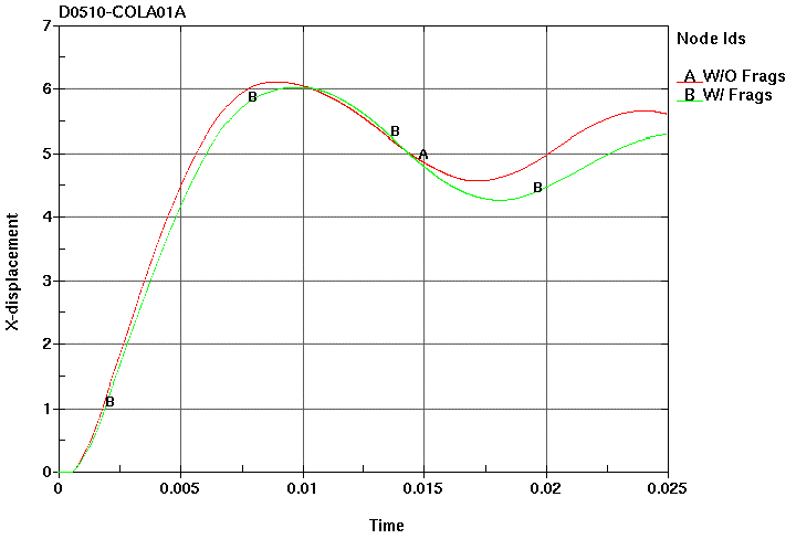
(b) Computed centerline displacement history.
Figure 2-12. Loading methodology for the column model without exterior cladding (Cases 2 and 3 in Figure 2-1b). Note that this procedure will require a Supplemententeary FRM to determine the damage to the steel due to fragments.
A general algorithm has been developed by Samhoon to generate realistic fragment patterns striking a component’s face. This code automates the methodology found in the P-397 manual [1], which relies on the Mott equation to calculate average fragment mass and on the Gurney equation to calculate fragment velocity.
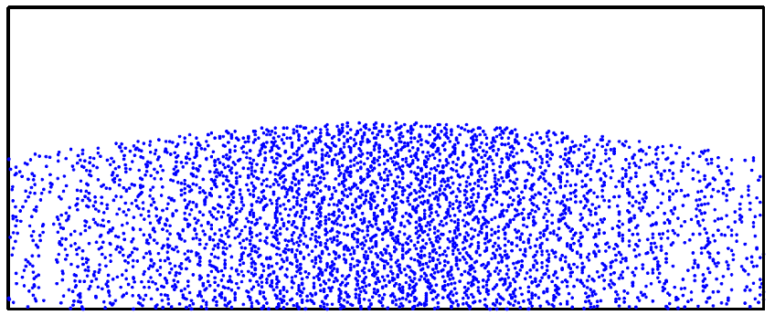
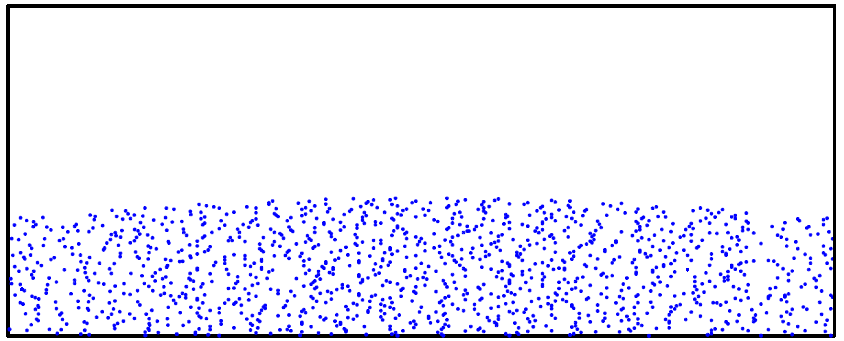
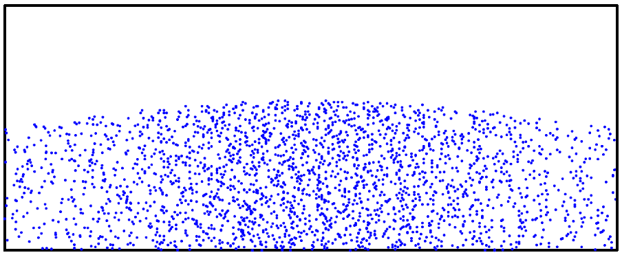
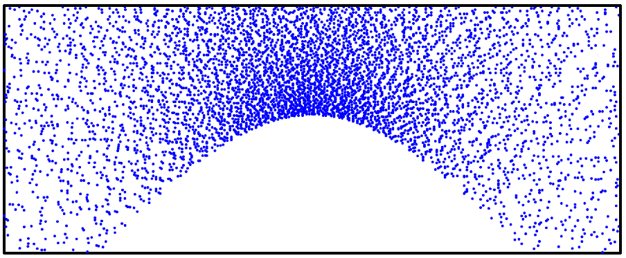
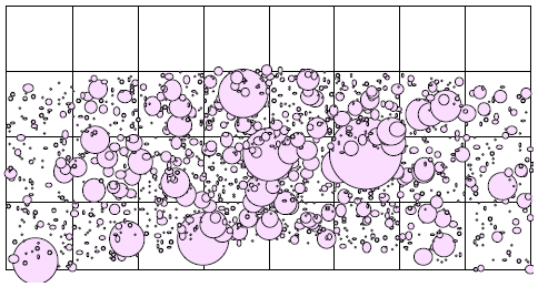
Samhoon proposes to enhance this basic approach by adding a distribution on the velocity, as well as randomizing the directionality of the individual fragments and imparting to them some component of velocity along the bomb’s axis to account for the effects of tail detonation. Once the starting position, mass, and velocity vector of each fragment is determined, our algorithm will compute its trajectory and point of impact against the face of a structural component. A series of plots showing typical fragment impulse patterns striking against a wall is shown in Figure 2-13. In Figure 2-14, results for two typical scenarios are shown:
◦One scenario is for a munitions oriented vertically in front of the wall (e.g., as shown in Figure 2-1b), which produces the slightly downward curving arc that delineates the edge of the region being impacted, which results from the downward spray caused by tail detonation.
(a) Case 1 (standoff = 15 feet) Ifrag = 0.63 psi-s.
(b) Case 15 (standoff = 30 feet) Ifrag = 0.22 psi-s.

(c) Case 273 (standoff = 4 feet) Ifrag = 0.88 psi-s.
Figure 2-13. Fragment patterns.
(d) Case 7 (alpha = 45) Ifrag = 0.54 psi.s
(e) Case 191 (Dcase = 6 inches) Ifrag = 0.13 psi-s.
(f) Case 339 (standoff = 6 feet, beta = -64) Ifrag = 0.48 psi-s.
Figure 2-13. Fragment patterns (Continued).
(a) Vertical weapon orientation. 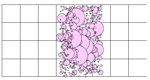
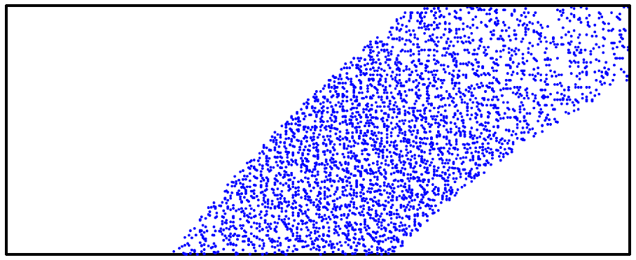
(b) Horizontal weapon orientation.
Figure 2-14. Fragment impulse patterns on a wall.
The other scenario shown is for a munitions oriented horizontally, and lying on the floor with its axis parallel to the wall.
The other scenario shown is for a munitions oriented horizontally, and lying on the floor with its axis parallel to the wall.
The size of the circle depicting an individual fragment hit is related to the magnitude of momentum imparted.
2.2.2.5 TASK 2.5: FRAGMENT LOADS
Once the mass and velocity of the fragments are defined, it is necessary to predict the effects of those fragments on the structural component. Two separate approaches are used; one involving flying the fragment, the other involves computing an equivalent triangular pressure pulse that may be applied to an analytic model of the member.
2.2.2.5.1 Equivalent Loads
Equivalent pressure histories computed to simulate fragment effects, which were generated for previous Samhoon efforts, typically have peak magnitudes on the order of 200,000 to 500,000 psi, and a duration of 10 to 50 µsec. An example of the early time deformations caused by these loads on an RC wall is shown in Figure 2-15, where the localized crater like deformations at the location of each significant fragment impact are depicted.
Figure 2-15. Example of the type of damage caused to RC walls. Here, the early time deformations (exaggerated 20×) in RC wall exposed directly to casing fragments are shown at 2 ms after their arrival.
2.2.2.5.2 Direct Impact
The direct approach of including fragments is illustrated by the bare steel column response shown in Figure 2-12. Since steel column sections are built from plates that are quite thin (ranging from 0.25 inches to 1.5 inches thick), many of the high energetic fragments are expected to perforate the plates of the column (e.g., as shown in Figure 2-12). Past calculations using the equivalent fragment loads indicated that the equivalent pressure pulse methodology produced poor results.
Instead, it is necessary to compute the damage and loading caused by the fragments directly. A loading procedure was developed for this effort, which is illustrated in Figure 2-12.
Here not only are the casing fragment characterized, but the effect on the member is also characterized, in that the fragment loading is computed in a manner suitable for direct application to the column’s surface.
This is done in such a way as to account for the mass, velocity, and angle of incidence of the fragment. Based on the thickness of the steel section and each fragment impact, the damage and the imparted impulse are computed and applied at each of the fragment impact locations.
This approach was used to generate the results shown in Figure 2-12a.
The primary feature of the approach used here is its ability to redefine the parameters of the analytic model of the member to reflect the holes caused by the fragments (i.e., the fragment damage pattern is incorporated explicitly in the analytic model).
In this study, there was a negligible difference between the column model with fragment damage (i.e., a model analogous in appearance to Swiss cheese) and a column model without fragment damage.
However, it is clear that this is not always the case.
At a much closer standoff or use of a lighter section may result in an entire region of the column being destroyed.
2.2.2.6 TASK 2.6: GENERATE TYPES OF COMPREHENSIVE LOADS
All the types of the load will be converted to element-based time histories for the application to the finite element model for the analysis. Comprehensive load are separated into two types of loads such as, pressure from air-blast and impact load from fragment or rigid body impact. Resultant load will be applied directed to the structural model for the prediction of behavior.
2.2.3 Task 3: Load Tuning
For the validation of generated load, preliminary structural analysis will be conducted. When the load is successfully matched to the observed phenomenon, it can be used for the next task of structural analysis with various parameters. Components such as steel door may be included in this phase of effort. Validation can be done by comparison of behaviors. Simplified fast running model will be used for trial-and-adjustment to tune the loading. Resistant function example for the FRM is shown in Figure 2.16.
(a)Classic form for resistance function (represented by the blue line) pertaining to the fully ductile
response or RC components to blast (i.e., where shear behaviors do not govern).

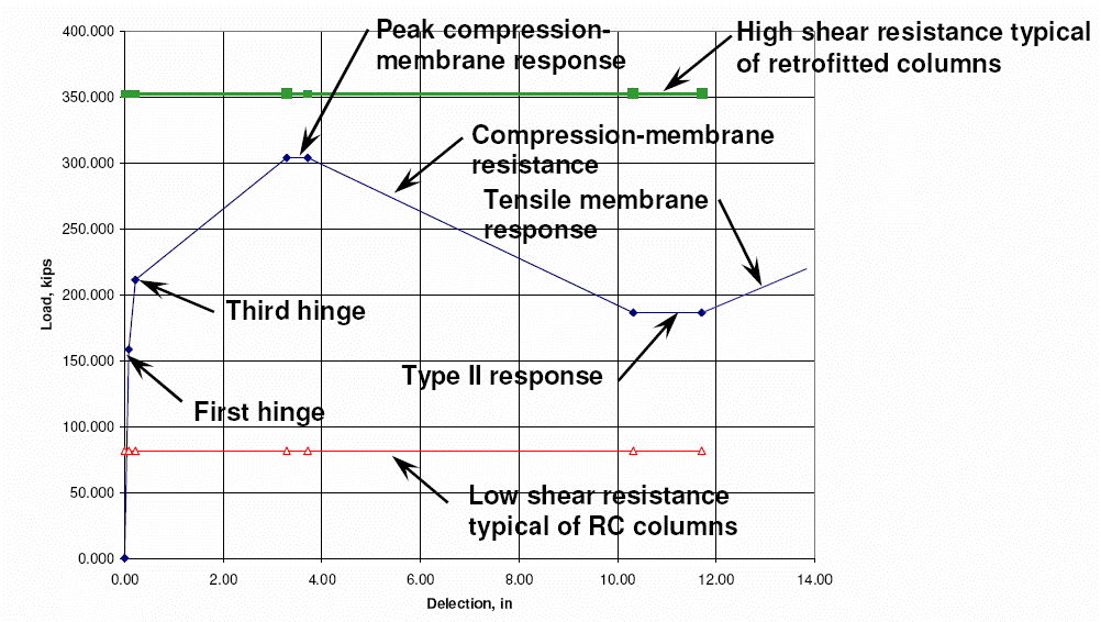
(b) Typical resistance function plot, which indicates the type of column behavior inherent in the
particular column’s design independent of blast loading. The response under the
blast load (i.e., computed maximum deflection) is also shown on this plot.
Figure 2-16. Examples of flexure resistance functions generated for use in the SDOF model.

(c) Effect of two hoop wraps on column resistance plot illustrates that the increase
in shear capacity due to wrap allows realization of full flexure resistance.
(d) Columns without axial resistraint, which results in a Type I and Type II resistance function.
Figure 2-16. Examples of flexure resistance functions generated for use in the SDOF model(Continued)
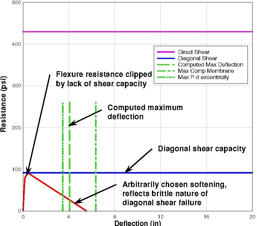
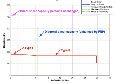
(a)Typical form of resistance function where diagonal shear failure governs behavior.

(a) Resistance function influenced by direct shear response, where initial portions resistance related to flexure, which transitions into a direct shear beginning at δp
Figure 2-16 Exmples of resistance functions that represent a combination of flexure and shear behaviors
2.2.4 Task 4: Structural Analysis – Parametric Study
Produced comprehensive load from Task 3 will be applied to the analysis model in this phase. High fidelity physics based finite element model (HFPB) will be established for the prediction analysis. Case of simulation will be defined and conducted for the consideration of various situations. Types of structural response will be considered as factors and responses of structural design.
2.2.5 Task 5: Design Structure
Based on the internal force response of the structure in the parametric study, cases of the appropriate response for the structure will be applied for the structural design. Relevant US design codes will be followed for the detail design.
2.2.6 Task6: Documentation
A technical report will be generated to document the works developed in Tasks 1 to 5, which will include for-construction-drawings.
2.3 PLANNED METHODOLOGY TO TRANSITION TO PRODUCTION AND RELATED RIGHTS
Transitioning to production is considered to be relatively straightforward. The technology developed under this proposal, including the analysis and design procedures and software, will be made unconditionally available to customer.
customer will have the sole right to release the product for use by the government agencies or public as it wishes.
However, Samhoon retains the copyrights to the technology and the rights to use the technologies developed under this project for further study and other projects.
Figure 2-17. Incident and reflected positive blast wave parameters for spherical charges of TNT in free air
Z = 1m/(10kg)^0.333=0.465
Pr = 1000 Mpa (Reflected wave Pressure)
Qs = 55 Mpa (Pack Dynamic Pressure)
Modular Design Concept(Extremely High Pressure Load)
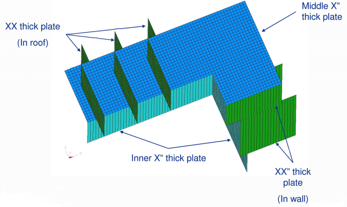
Steel in Structure 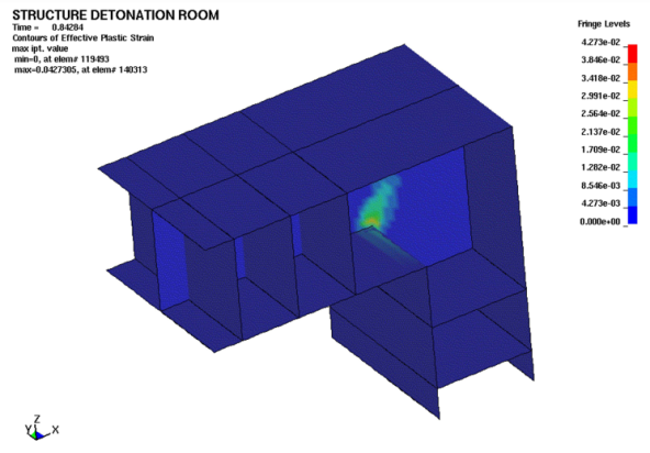
Plastic Strain in Plates
(Refer to separate proposal provided by SAMHOON for Extremely High Pressure Load.)
SECTION 3
SCHEDULE,COSTS AND DELIVERABLES
3.1 SCHEDULE
Samhoon proposes to carry out this project in two phases:
□ Phase I – All the informative calculation will be done in this phase. Loading will be generated and structural analysis will be done. Also, technical report will be delivered to the owner of this project. Time for Phase I is proposed 1.5 months.
□ Phase II – Another one month for structural design testing and modifying the software based on user feedback. The final technical report will be submitted.
3.2 COST AND PAYMENT SCHEDULE
1.PROJECT NAME : R & D EXPLOSION CELL DESIGN
2.DELIVERY : 90 DAYS
3.A TERM OF VALIDITY :3 MONTHS
4. PAYMENT TERMS : ADVANCE 50%, AFTER 50%
5. DETAILS
A. BLAST PRESSURE INSPECTION:
B. CALCULATION:
B. DESIGN OF DRAWING:
D. SIMULATION REPORT:
E. DOCUMENTS:
F. TRAVELLING EXPENSES:
Total :
(Details of COST AND PAYMENT SCHEDULE can be adjusted by agreement.)
SECTION 4
REFERENCES
1. "Structures to Resist the Effects of Accidental Explosions," Departments of the Army, the Navy, and the Air Force, Army TM 5-1300, Navy NAVFAC P-397, Air Force AFR 88-22, Washington, D.C., November 1991.
2. "A Manual for the Prediction of Blast and Fragment Loadings on Structures," Department of Energy, DOE/TIC-11268, August 1981.
3. Meyers, M. A., "Dynamic Behavior of Materials," 1994.
4. Zukas, J. A., "High Velocity Impact Dynamics," 1990.
5. Bulson, P. S., "Explosive Loading of Engineering Structures," 1997.
6. Cooper, Paul, "Explosives Energy," Wiley, 1996.
7. Kinney, G. F. and K. J Graham, "Explosive Shocks in Air," Springer-Verlag, New York, 1985, p. 81.
8. "Prevention of And Protection Against Accidental Explosion of Munitions, Fuels and Other Hazardous Mixtures," Annals of the New York Academy of Sciences, Volume 152, Art. 1, October 1968.
9. Smith, P. D. and J. G. Hetherington, "Blast and Ballistic Loading of Structures," 1994.
10. "Structural Design for Physical Security State of the Practice," American Society of Civil Engineers, 1999.
11. "Design and Analysis of Hardened Structures to Conventional Weapons Effects," Joint Departments of the Army, Air Force, and Navy and the Defense Special Weapons Agency, UFC 3-340-01, June 2002.
12. Crawford, J. E., L. J. Malvar, J. M. Ferritto, K. B. Morrill, B. W. Dunn, and P. Bong, "Description of Design Software for Retrofitting Reinforced Concrete Columns to Improve Their Resistance To Blast," Karagozian & Case, Burbank, CA, TR-01-16.3, October 2003.
13. Drake, J. L., L. A. Twisdale, R. A. Frank, W. C. Dass, M. A. Rochefort, R. E. Walker, J. R. Britt, C. E. Murphy, T. R. Slawson, and R. H. Sues, "Protective Construction Design Manual," Final Report, ESL-TR-87-57, November 1989.
14. "Fundamentals of Protective Design for Conventional Weapons," TM 5-855-1, U.S. Department of the Army, Washington, D.C., 1994.
15. Kingery, C. N., and G. Bulmash, "Airblast Parameters From TNT Spherical Air Burst and Hemispherical Surface Burst," ARBRL-TR-02555, Ballistic Research Laboratory, Aberdeen Proving Ground, Aberdeen, MD, April 1984.
16. Wager, P., "Documentation for SHOCK & FRANG Airblast Software, 1976.
17. Bogosian, D. D., "Review Comments on BLASTXW, Version 3.6.2.0," Karagozian & Case, Burbank, CA, TM-96-39.1, December 1996.
18. Britt, R. J., D. E. Ranta, and C. E. Joachim, "BlastX Code, Version 4.2, User’s Manual," ERDC/GSL TR-01-2, USAE Engineer Research and Development Center, Geotechnical and Structural Laboratory, Vicksburg, MS, March 2001.
19. Hyde, D. W. "User’s Guide for Microcomputer Programs ConWep and FunPro, Applications of TM 5-855-1, ‘Fundamentals of Protective Design for Conventional Weapons,’" Instruction Report SL-88-1, Department of the Army, Waterways Experiment Station, Corps of Engineers, Vicksburg, MS 1988.
20. Crawford, J. E. and S. Lan, "Development of Analysis/Design Procedures and Software for Reinforced Concrete Beams and Columns Related to their Resistance to Blast Effects from Cased Explosives," Karagozian & Case, Burbank, CA, TR-06-48.1 October 2006.
21. ASCE 9th : Blast Resistant Design of Buildings
22. Technical proposal submitted to SAMHOON by Ph.d Hyung-Jin Choi in 2009
23. Planning Guideline for Chemical Warfare Defense Military Facility
24. TM5 855-1 : Fundaments of Protective Design for Conventional Weapons
25. TM5 858-1 : Design Facilities to Resist Nuclear Weapon Effects ; Facilities System Engineering
26. TM5 858-2 : Design Facilities to Resist Nuclear Weapon Effects
27. TM5 858-3 : Design Facilities to Resist Nuclear Weapon Effects ; Structures
28. TM5 858-5 : Design Facilities to Resist Nuclear Weapon Effects ; Air Entrainment, Fasteners, etc.
29. TM5 858-6 : Design Facilities to Resist Nuclear Weapon Effects ; Hardness Verification
30. TM5 858-7 : Design Facilities to Resist Nuclear Weapon Effects ; Facility Support Systems
31. TM5 858-8 : Design Facilities to Resist Nuclear Weapon Effects ; Illustrative Examples
32. UFC 3-340-02(STRUCTURES TO RESIST THE EFFECTS OF ACCIDENTAL EXPLOSIONS)
33. ASTM F 2247(Standard Test Method for Metal Doors Used in Blast Resistant Applications Equivalent Static Load Method)
34. ASTM E 283(Standard Test Method for Determining Rate of Air Leakage Through Exterior Windows, Curtain Walls, and Doors Under Specified Pressure Differences Across the Specimen)
35. AWS D1.1 : STRUCTURAL WELDING – STEEL
36. SHQAM(SAMHOON QUALITY ASSURANCE MANUAL)
37. Test Report for ASTM F 2247(SSW/367/2012 Rev.7 dated 28. 8.2015/15.7 PSI)
38. Test Report for Blast Valve(LRS-37844/2011/ 3 BAR)
39. SAMHOON Qatar Sliding Blast Protection Door SSD-01, Blast Simulation Analysis Report #480-BAR-R20211223 |Release: R6, December, 23rd, 2021
40. SAMHOON Qatar Swing Blast Protection Door SD08, Blast Simulation Analysis Report
#480BARR20211027|Release:R2,November, 11th, 2021
28. TM5 858-5 : Design Facilities to Resist Nuclear Weapon Effects ; Air Entrainment, Fasteners, etc